
Introduction
This guide details how to install U.S. Robotics V.92 56K Modems (Model: 5686G). These modems
are used as part of a ‘Dial-Up Chain’ which allows communication between the Symmetry Node and
Symmetry server. An M2150 Node was tested with Symmetry V8.
This guide is tailored towards engineers with adequate levels of Symmetry knowledge.
Remote Modem Configuration
The Remote Modem is the modem connected to the Node.
Cabling
A standard serial connection is required where the serial port on the modem is wired to the COM C or
RS-232 port on the Node. The wiring diagram for connecting the modem to the Node is detailed in the
Node’s installation manual.
The remote modem must be first connected to a PC for programming as detailed further below.
Dipswitch Settings
On the back of the modem are eight dipswitches. These must be set as follows:
- Down (ON)
- Down (ON)
- Down (ON)
- Down (ON)
- Up (OFF)
- Up (OFF)
- Up (OFF)
- Down (ON)
The Node also has a series of dipswitches which should be set to enable the COM C or RS-232 port
as the connection to the Host PC – this is detailed further in the Node’s installation manual.
Programming Strings
For programming, the modem needs to be connected to a PC using a serial COM port. A standard 9-
PIN RS-232 connection is required. The PC’s COM port must have all settings left at default, including
8 data bits, no parity, 1 stop bit, no flow control and 9600 baud rate.
The modem needs to be initialized with a programming string. This string is made up of a number of
commands. Each command turns on or off a setting within the modem, an example of this is the
command &N6 which sets the modem to 9600 baud rate.
HyperTerminal (or similar) is required to send the programming commands to the modem.
HyperTerminal is included in Windows XP but is not available in the latest version of Windows.
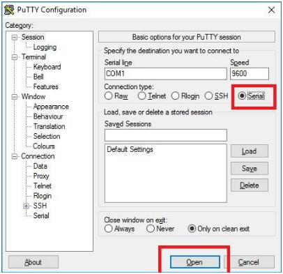
A third-party application is available for later operating systems called PuTTY. This can be
downloaded here (as of the date of this article):
http://www.chiark.greenend.org.uk/~sgtatham/putty/latest.html
Once PuTTY is installed select Serial and then Open. As detailed previously, if the COM port
configuration is default then no settings require changing.
If Symmetry is installed on this machine make sure the SMS Client Service is stopped as this may be
trying to connect out on the same port which will ultimately block the connection.
A command window will appear, enter the following command and press Enter:
AT&F1
An OK message should be displayed under the command. This has cleared out the modem’s current
configuration. If an error is generated then the cabling or port configuration is incorrect or the COM
port is blocked.
Next, type the following command and press Enter:
ATVS0=2EX&D&M&N6&R1&W
The first letter of the command (A) should turn to 0 indicating the command has been accepted by the
modem. If 3 or 4 are displayed then the modem has not accepted the string and the string will need to
be re-entered. You may need to re-run the AT&F1 command to clear the configuration and try again.
Host Modem Configuration
The Host Modem is the modem connected to the server.
Cabling
A serial connection is required where the serial port on the modem is wired to the COM port on the
server. As covered, the COM port must have all settings left at default. The wiring standard for
connecting the modem to the PC is detailed further in the modem’s installation manual but uses a
standard 9-PIN RS-232 connection.
Dipswitch Settings
On the back of the modem are eight dipswitches. These must be set as follows:
- Up (OFF)
- Down (ON)
- Down (ON)
- Down (ON)
- Up (OFF)
- Up (OFF)
- Up (OFF)
- Down (ON)
Programming Strings
As detailed for the remote modem a programming string needs to be entered into the host modem
using HyperTerminal or PuTTY.
The following string needs to be programmed in the same way:
AT&F1
An OK message should be displayed.
Next, type the following command and press Enter:
ATQVS0=1EX&D2&M&N6&W
A should change to 0.
Symmetry Configuration
The following is to be conducted in the Symmetry software.
Symmetry Dial-Up Chain
Make sure a ‘Multinode Dial-Up Chain’ Client Port is created with 9600 Baud.
Under the Install | Chains | Dial-Up menu, create a Dial-Up Chain as detailed on the next page.
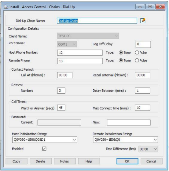
Complete the Chain Name and Phone Number fields as required.
The Host and Remote Initialization Strings must be set to the top options as shown in the image. For
example:
Host Initialization String = Q0V0S0=1E0&Q0
Remote Initialization String = Q0V0S0=1E0&Q0
Finalization
The Node and Readers can now be added into Symmetry and connection between the modems
tested. If Node Status is opened, this will initiate a call between the server and Node. If the server has
initialized the modem, the AA, TR and CS LEDs will be illuminated on the front of the host modem.
The modem should disconnect if no request is being from the software. The modem should also start-
up a connection to the server if an alarm is generated on the Node.
Limitations
A limitation was found where on some occasions the modem would not disconnect the call after a
loss of activity in Symmetry. This was intermittent and is related to the string programming. It is worth
checking and re-entering the strings in the modem and making sure the default initialization strings
have been selected in the Dial-Up Chain menu as covered above.
‘Enable Learn-Mode During Card Download’ – this option presented some trouble on the initial
connection and is best left off during the configuration phase. It can be enabled afterwards.
Comments
0 comments
Please sign in to leave a comment.